SIGHT
サイト

SCOPE
スコープ

STABILIZER/V BAR
スタビライザー・Vバー

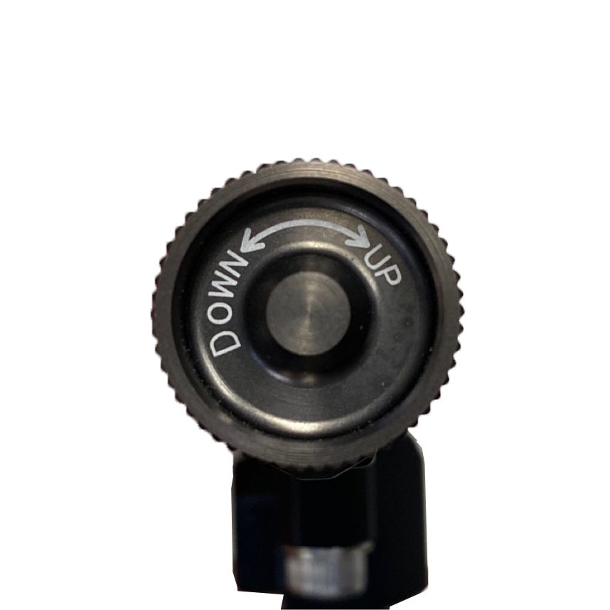
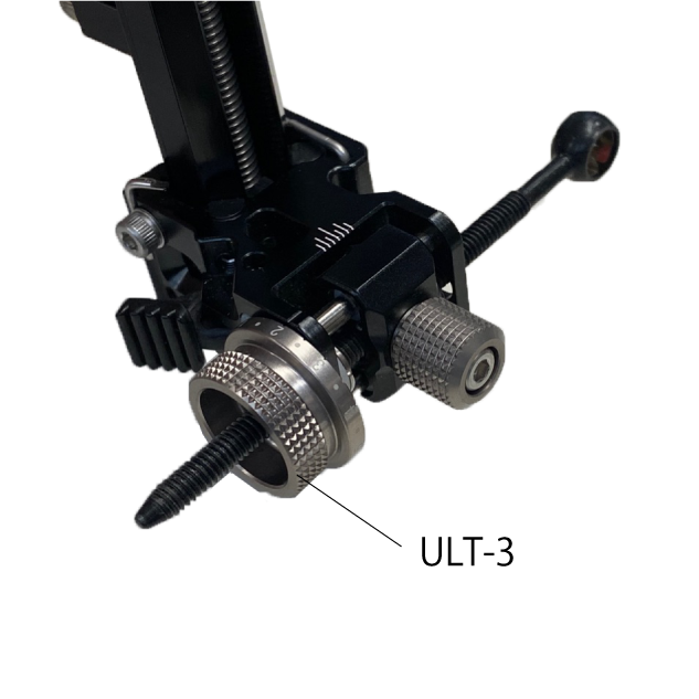
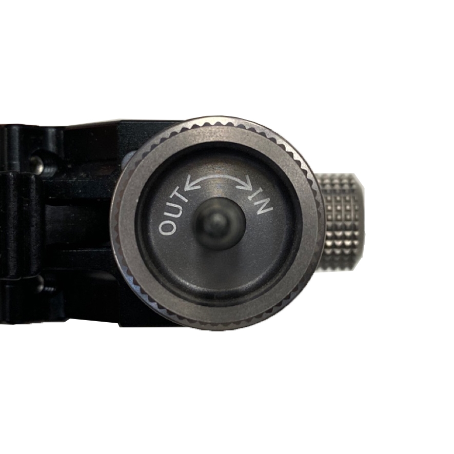
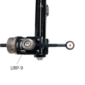
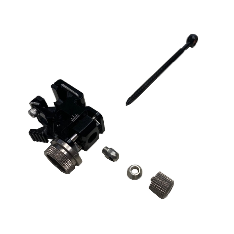
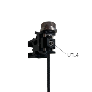
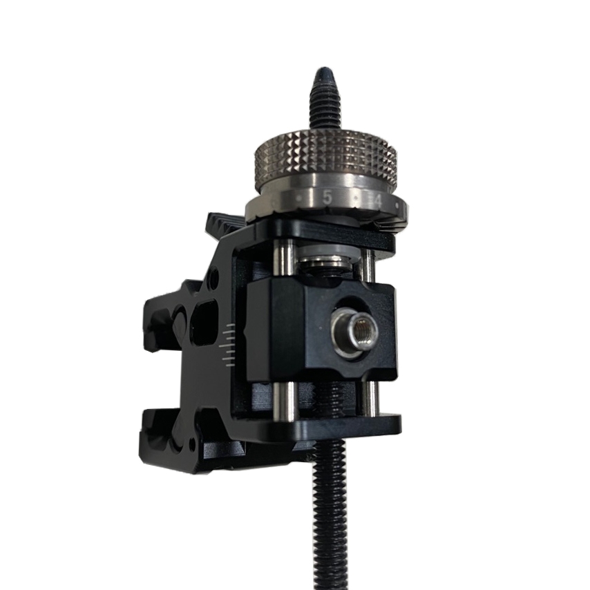
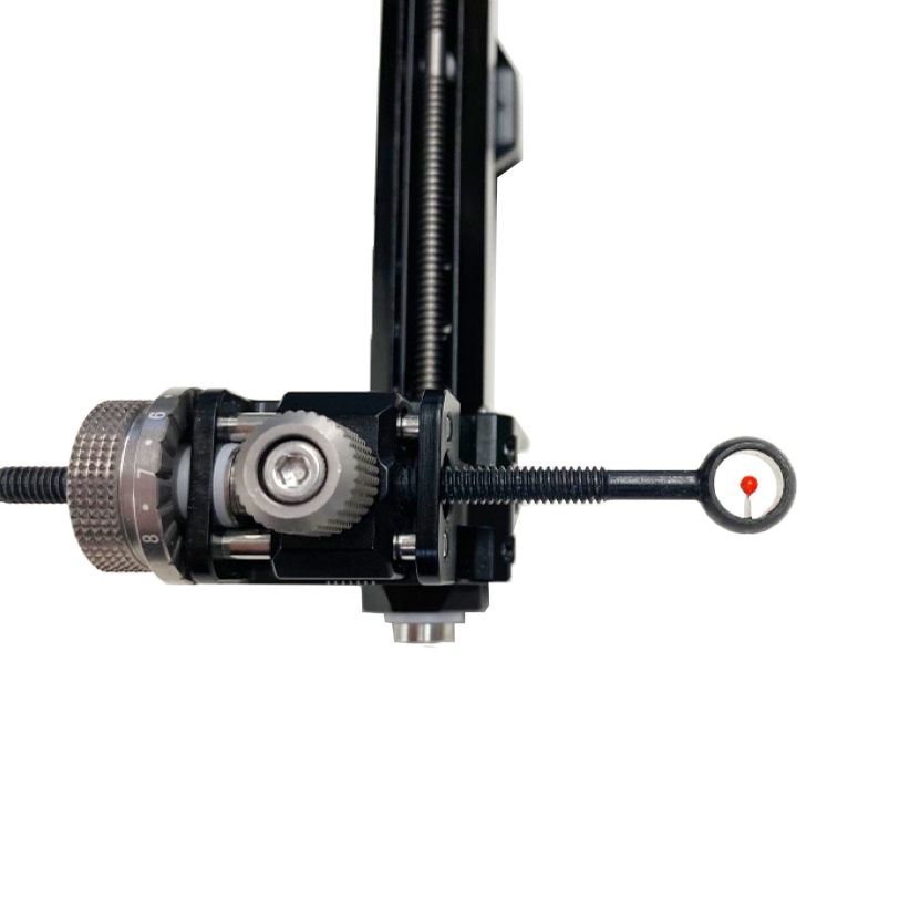
REST/PLUNGER
レスト・プランジャー

TAB
タブ
OTHERS
その他
サイト
スコープ
スタビライザー・Vバー
レスト・プランジャー
タブ
その他